.jpg)


QUANTAR, POSITION SENSITIVE, IMAGING DETECTOR SYSTEMS
Quantar Technology's 3300/2400 Series Multi-channel/ Multi-pixel ImagingTM Detector Systems are position sensitive, quantum-limited, charged-particle and photon detectors designed primarily for scientific, analytical and industrial research applications involving spatially-resolved analysis of events occurring from inherently weak signal-generating processes, demanding high detector performance. These high performance, position sensitive detectors are ideal solutions in a wide range of 1D parallel multi-channel spectroscopy and 2D X-Y imaging applications. Complete systems comprise a MCP/RAE position sensitive detector head, signal processing and readout electronics, and PC-based data collection and display hardware and software.
3300 Series MCP/RAE Open-Face Sensors (OFS/detector heads) utilize MCP (micro-channel plate) imaging electron multipliers followed by a charge-division position senstive, encoding resistive anode. Operating in high vacuum environments, these detectors provide true, single-event counting, position sensitive detection of electrons, positrons, positive and negative ions, energenic neutral particles and EUV and soft X-ray photons (10-200 nm) directly on the MCP input surface. Higher energy X-rays (>2 KeV) can also be detected directly by MCP's with decreasing efficiency at higher energies. Detection efficiency for various types of particles and photons is determined primarily by the MCP surface response and/or by applied enhancement coatings.
Combined with use of our 2401B Position Analyzer and with extremely-low detector MCP background dark count (typically less than 10 counts/sec over entire active area), these MCP detectors are capable of offering extremely high signal-to-detector-background ratio measurements, especially useful in relatively low count-rate applications, where signals of interest would otherwise be obscured by noise.
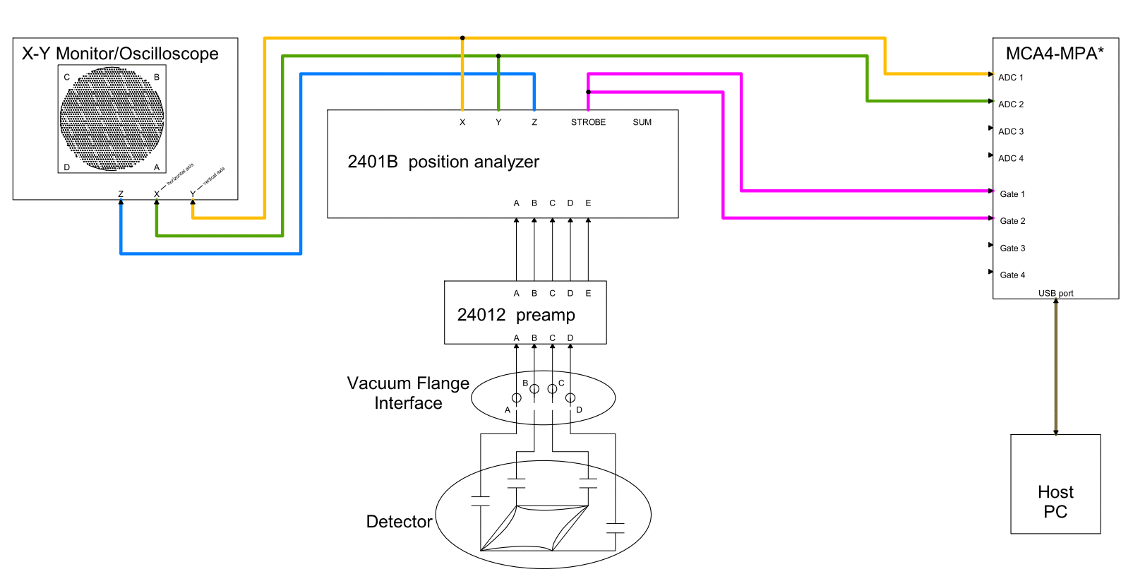
The Model 2401B is a 2 axis (X, Y), pulse-position processor consisting of a separate, 4-channel input, charge-sensitive preamplifier/shaper module with added fast look-ahead channel output and a main electronics module (19" rack mount unit) containing signal processing, metering, edge-gating and power supply circuits. Designed to be used with a 3300 Series position sensitive MCP/RAE based detectors; two preamp gain options are available to match MCP/RAE sensor head types. The position analyzer has a count rate capability of up 100,000 counts/sec for Poisson arrival distributions, as is usually seen in applications, and has real-time display capabilities to monitor events as they occur.
The latest data systems for use with the 2401B position analyzer are based on the FAST ComTec multiparameter (MPA) systems and form a complete position sensitive detector system. There are three primary models, the MPA-3, MPA4 and MCA4-MPAx systems, which can all be used with the 2401B to collect a simple two parameter, X&Y position data set. For these setups, the 2401B X and Y analog position signals along with the STROBE signal are used with a system, operating in a sample voltage analysis (SVA) mode. The STROBE is used to trigger a compatible ADC, defining when the data event is sampled and recorded (using SVA mode, rather than a traditional peak detection).
FAST ComTec Products
Fast ComTec GmbH Scientific Instruments.
PC-based multichannel analyzers, multiparameter analyzers, time multichannel
scalers, NIM and bench-top HV power
supplies, NIMBINS and other NIM pulse processing instrumentation.
| |
| Home | Quantar Products | FAST Products | Support/Service | Contact Us | About Us |
|
Quantar Technology Incorporated - 2620A Mission Street, Santa Cruz, CA 95060-5703 Tel/FAX: 831-429-5227 · www.quantar.com |